SIL Calculations: Determining the Probability of Failure on Demand

by Chet S. Barton, P.E., FS Exp (TÜV Rheinland)
There is inherent risk in industries that handle hazardous materials or processes where an equipment failure could endanger people, communities, or the environment. In accordance with industry standards, equipment must be designed for the appropriate level of reliability and robustness to achieve the required risk reduction. A safety integrity level (SIL) calculation, part of safety design for hazardous processes, ensures that safety systems meet the required risk reduction for identified hazards.
Risk Assessment
A hazard and risk assessment, or process hazard analysis (PHA), must be completed to identify and assess potential hazards and their associated risks. A methodology called layers of protection analysis (LOPA) quantifies the determined risks. Independent layers of protection (IPL) are then designed to mitigate or reduce the risk to an “acceptable” level by either preventing the accident altogether or minimizing the effect if one does occur.
IPLs are designed to be independent both from the initial cause of the hazard and from each other. A safety instrumented function (SIF), part of a safety instrumented system (SIS), is a type of IPL.
Example
A chemical manufacturing plant conducts a PHA. The LOPA risk assessment shows that a high-pressure event in a reactor could cause an explosion, posing significant danger to workers, equipment, and the surrounding community. The SIS monitors the reactor pressure and activates the SIF when high pressure is detected. When the SIF sensors detect high pressure, the automated control system performs an action that relieves the pressure, mitigating the risk of explosion.
Safety Integrity Levels
International Electrotechnical Commission (IEC) 61511 issues safety and equipment verification requirements for process or high-hazard industries such as chemical manufacturing and oil & gas. Based on these requirements, the target level of risk reduction is identified for the safety elements in the process. This target level of risk reduction is called the safety integrity level . SIL calculations are used to verify if an SIF was designed properly to meet the required level of risk reduction. SIL levels range from SIL 1 (least hazardous process requiring least risk reduction) to SIL 4 (most hazardous process requiring most risk reduction).
It’s most cost-effective for the verification to occur after the conceptual equipment design but before any detailed design work has been completed (and before any modifications to the system). If the initial design doesn’t meet the requirements, it’s easier and less expensive to update the design of the controls and equipment before making any purchases.
Historically, complex mathematical calculations were required to determine whether the designed IPLs met the required SIL for the system. Today, there are multiple software packages available to the process engineer to streamline this calculation (exSILentia by exida, SIL Solver by SIS-TECH).
Probability of Failure on Demand
Fundamental to the SIL calculation is the probability of the safety equipment’s failure on demand (PFD). If a hazardous event were to occur, the PFD is the likelihood that the SIF, the equipment or software designed to mitigate that particular risk, will fail.
A SIF’s inherent probability of failure naturally increases over time as the equipment ages. When the SIF is tested, the average probability of failure decreases because the equipment is proven to function properly. The PFD then increases until the next testing interval. Device manufacturers typically provide a base PFD for a device derived from the equipment’s specifications, representing the PFD when the equipment is new.
Calculating the Probability of Failure on Demand
To verify that the equipment meets the required SIL, the probability of failure on demand must be calculated for each safety instrumented function (SIF) in the safety hierarchy. The SIF’s average PFD is comprised of the average PFDs for the sensor, the logic solver, and the final element. Seven parameters (as shown below) are required to calculate each average PFD and must conform to RAGAGEP, Recognized and Generally Accepted Good Engineering Practice, as defined by the Occupational Safety and Health Administration (OSHA).
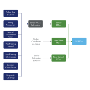
- The failure rate of the device is the frequency the device fails, expressed in failures per hour. Equipment failure rates are published in several reference guides and are also normally available from the equipment’s manufacturer as tested by an independent testing agency.
- The voting arrangement describes how a logical decision will be made when multiple sensors or other input data may not agree on whether an abnormal condition exists. The voting arrangement is programmed into the logic solver and is determined in the design phase, depending on your circumstances and process.
- Service/environmental factors affect the reliability of the components, including operating conditions such as temperature, humidity, vibration, and exposure to corrosive substances. Resources, such as the American Institute of Chemical Engineers (AIChE), provides guidelines for which number to use depending on the environmental conditions.
- The proof-testing interval refers to the amount of time between proof tests of the equipment. This is typically one year but varies due to the nature of the process and equipment. The more dangerous or riskier your process, the more often you should test. The shorter the interval, the lower the probability of failure. A regular and consistent proof testing interval and adherence to the equipment manufacturer’s specified maintenance protocols should be maintained.
- Proof-testing effectiveness is a measure of the proof tests’ effectiveness to uncover hidden faults in a safety instrumented system. This is typically 95% or less, as it’s impossible to guarantee that the proof test will find every potential fault. The equipment manufacturer will use a third-party firm to certify their equipment. The firm will provide guidelines on how to test that component and the effectiveness of the test.
- The common cause factor is similar to the environmental factor. It is usually represented as a percentage to account for circumstances where multiple components—physical, software glitch, or otherwise—will fail simultaneously due to a shared cause or that an unforeseen error, including a human or manufacturing error, has occurred. This is typically 1-2%. AIChE guides this but does not define what it has to be.
- Diagnostic coverage is the percentage of potential failures that can be detected and diagnosed by the SIS or SIF during regular operation, without the need for external testing. In modern systems, diagnostic coverage is typically around 95%, as they are equipped with internal self-diagnostics and reporting functions.
SIL and Risk Reduction Factors
The target SIL from the PHA/LOPA defines the required PFD value (as shown in the IEC 61511 SIL Table). Once the SIF average PFD has been calculated, you can determine if the SIF meets the required risk reduction. The SIF availability range is the required percentage of uptime expected from the safety instrumented function. The risk reduction factor (RRF) is the inverse of the SIF average PFD range and illustrates how much the SIF reduces the risk of a hazardous event. If the equipment as designed does not produce the required level of risk reduction—a SIL 2 was calculated, but you need a SIL 3—then you need to revisit your conceptual design.
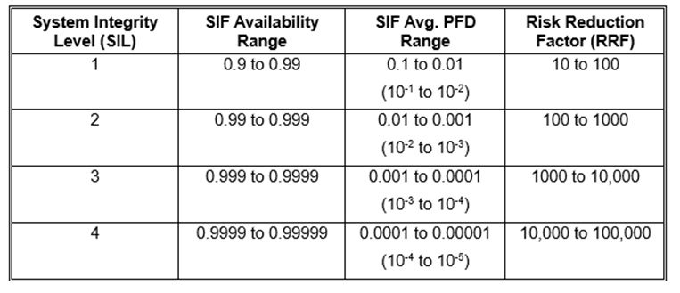
(IEC 61511 SIL Table)
Experience shows that it’s typically the final element that contributes to the system not reaching the required SIL. For example, a valve tends to corrode and get stuck in place or won’t close completely. Examining the safety system shows that the valve contributes to the lower SIL; replacing it with a higher-duty version can increase the SIL for the entire system.
An Experienced and Qualified Control System Integrator
Hargrove Controls & Automation has years of experience designing safety systems to protect against hazards. Our Team of TÜV Rheinland functional safety specialists can facilitate LOPAs, generate SIF conceptual designs, and perform SIL calculations so your facility is compliant and safe. Protect your people, community, and surrounding environment.
Contact us for more information or to discuss a specific project.